How can we help?
Having trouble? Click here to access our troubleshooting guide.
Your Question:
New User Interface Setup
CAUTION! Sensitive electrical components. Ensure that before touching any electrical parts you are discharged of any electro-static build up by touching an earthed metallic part (example: a copper tube or a radiator). Make sure that no water drops on to the electronics or the wiring.
DANGER! Mains voltage – Risk of electric shock. Turn OFF the power supply before working on the appliance and observe safe working practices.
www.glow-worm.co.uk
INDEX & IMPORTANT INFORMATION
SECTION 1 - Pages 3 – 6
To be used for the following models only:
18Si, 30Si, 24Ci, 30Ci, 35Ci
SECTION 2 - Pages 7 – 11
To be used for the following models only:
12Hxi, 15Hxi, 18Hxi, 24Hxi, 30Hxi, 38Hxi, 18Sxi, 30Sxi, 24Cxi, 30Cxi, 38Cxi, BG330, Xtramax HE
IMPORTANT INFORMATION - Once the new interface card has been fitted and set up correctly by following the information contained in this instruction sheet, you must ensure that all mandatory gas safety checks have been carried out on the appliance prior to leaving the property to ensure its safe operation in accordance with the standards.
For any appliance specific information (gas rate figures, combustion settings, fault codes etc), please consult the relevant Installation & Servicing manual for the appliance being worked on.
(Installation & Servicing manuals can be downloaded via the Glow worm website at www.glow-worm.co.uk if required)
SECTION 1 - FOR THE FOLLOWING STANDARD EFFICIENCY MODELS ONLY - 18Si, 30Si, 24Ci, 30Ci, 35Ci
Configuring the Interface Card
Once the replacement interface card has been fitted into the appliance, it is ESSENTIAL to perform the adjustment steps shown in this leaflet.
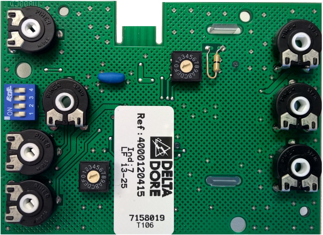
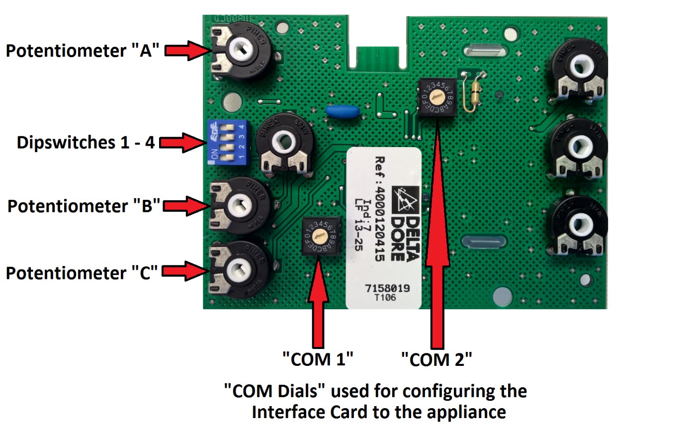
Diagram 1

STEP 1 – DIPSWITCH ADJUSTMENT
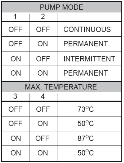
Table 1
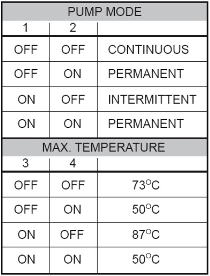
Using Diagram 1 on Page 3 and Table 1 above, set the Dipswitch positions in accordance with the system requirements.
NOTE – For normal systems using a regular high temperature radiator circuit, it is recommended that all the dipswitches are set to the ‘OFF’ position.
STEP 2 – CONFIGURING THE INTERFACE CARD TO THE APPLIANCE MODEL
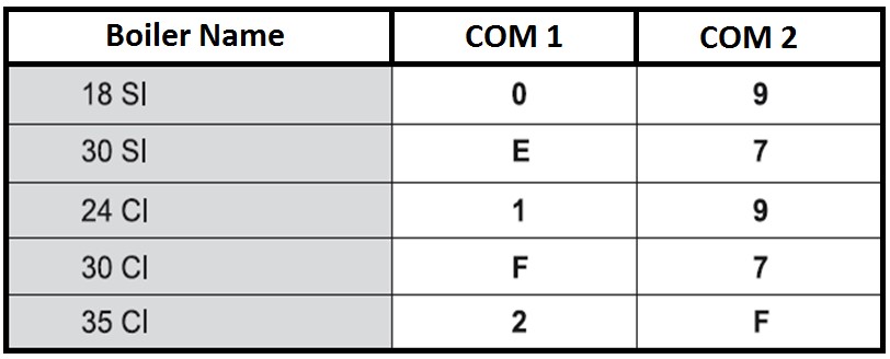
Refer to Diagram 1 on Page 3 and Table 2 below to configure the “COM 1” & “COM 2” dials to the positions relative to the appliance model
Table 2
STEP 3 – POTENTIOMETER ADJUSTMENTS
IMPORTANT! - Setting the minimum burner pressure
The minimum burner pressure will need to be adjusted after replacement of the interface card on the 18Si, 30Si, 24Ci, 30Ci & 35Ci models as follows:
Refer to Diagram 1 on Page 3 for potentiometer locations.
Turn Potentiometer “A” to the fully anti-clockwise position (10 ‘o clock)
Turn Potentiometer “B” to the fully anti-clockwise position (10 ‘o clock)
Fit a manometer onto the burner pressure test point on the gas valve.
Turn the appliance on for a central heating demand, and turn Potentiometer “B” slowly clockwise until the minimum burner pressure reading matches the value on the appliance data badge.
NOTE – Check for gas tightness on the gas valve burner pressure test point after removing manometer
IMPORTANT! – Setting the appliance heating kW output
Potentiometer “A” is used to adjust the central heating kW output on combination boilers (24Ci, 30Ci, 35Ci), and total kW output for system boilers (18Si, 30Si). On Potentiometer “A” the minimum kW output position is the fully anti-clockwise (10 ‘o clock) position and the maximum kW output position is approximately between the 12 ‘o clock and 1 ‘o clock position. When the boilers were originally manufactured they were set to a 15kW factory setting, this is in the 2 ‘o clock position on the new interface card (NOTE – The 15kW setting was the 10 ‘o clock position on the original versions of the interface card)
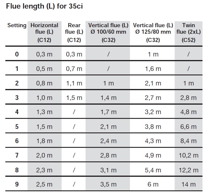
STEP 4 – SETTING THE FLUE PARAMETERS (35Ci MODEL ONLY)
This adjustment is made to ensure the 35Ci model operates at maximum efficiency when used with longer flue lengths.
NOTE – This adjustment must be done when the burner is OFF.
See Diagram 1 on Page 3 for potentiometer positions, and insert a small screwdriver into Potentiometer “C”
STEP 4 continued………
Slowly turn Potentiometer “C” clockwise whilst looking at the boilers digital display and the letter ‘A’ will appear on the display followed by a number as shown below. Turn the potentiometer slowly until you have the desired setting number for the flue system in accordance with Table 4 below:

(For example, the setting “A9”would mean the Horizontal Flue fitted to the appliance is 2.5 metres or more in length)
Table 4
THE INSTALLATION & ADJUSTMENT OF THE REPLACEMENT INTERFACE CARD IS NOW COMPLETE
(Carry out all post installation checks in accordance with the IMPORTANT INFORMATION section on Page 2 of these instructions)
SECTION 2 - FOR THE FOLLOWING CONDENSING MODELS ONLY - Cxi, Sxi, Hxi, BG330 & Xtramax HE
Configuring the Interface Card
Once the replacement interface card has been fitted into the appliance, it is ESSENTIAL to perform the adjustment steps shown in this leaflet.
Diagram 1
STEP 1 – DIPSWITCH ADJUSTMENT
Table 1
Using Diagram 1 on Page 7 and Table 1 above, set the Dipswitch positions in accordance with the system requirements.
NOTE – For normal systems using a regular high temperature radiator circuit, it is recommended that all the Dipswitches are set to the OFF position.
STEP 2 – CONFIGURING THE INTERFACE CARD TO THE APPLIANCE MODEL
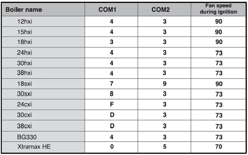
Refer to Diagram 1 on Page 7 and Table 3 below to configure the “COM 1” & “COM 2” dials to the positions relative to the appliance model:
Table 3
STEP 3 – ADJUSTING THE IGNITION FAN SPEED SETTING
IMPORTANT! This setting has to be carried out BEFORE trying to start the boiler as follows:
Turn the boiler temperature control knob(s) fully anti-clockwise
Turn ON the power supply to the boiler to activate the digital display
Consult Diagram 1 on Page 7 for potentiometer locations. Insert a small screwdriver into Potentiometer “B” and turn it slowly clockwise whilst simultaneously looking the boilers digital display until the number on the digital display matches the appliance specific “Fan speed during ignition” figure as shown in Table 3 on Page 8.
NOTE – The “Fan speed during ignition” figure is only shown on the digital display whilst Potentiometer “B” is physically being turned. When the potentiometer is stationary the display will be in a normal standby state (will show a bar pressure reading or the actual boiler temperature depending on model)
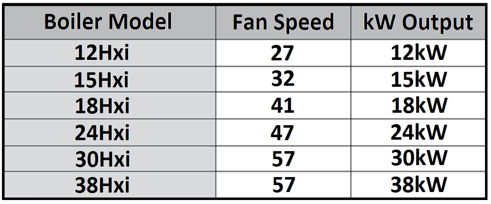
STEP 4 - kW OUTPUT ADJUSTMENT (Hxi Models ONLY)
(IMPORTANT!! – THIS ADJUSTMENT MUST BE CARRIED OUT ON THE HXI MODELS OTHERWISE THE APPLIANCE WILL NOT RUN WITHIN THE CORRECT MANUFACTURERS SPECIFICATIONS)
See Diagram 1 on Page 7 for potentiometer locations.
Ensure the boiler temperature control knob is turned to the maximum position and place a demand on the appliance. Once the boiler has fired, insert a small screwdriver into Potentiometer “C” and turn it fully clockwise to the 7 ‘o clock position. A flashing fan speed figure will be shown on the boiler display. Turn Potentiometer “A” slowly clockwise until the flashing number in the display matches the appliance specific “Fan Speed” number as shown in Table 5 on Page 10. Once the correct fan speed has been set, return Potentiometer “C” back to the fully anti-clockwise position. The digital display will then stop flashing and return to normal mode.
Table 5
THE INSTALLATION & ADJUSTMENT OF THE REPLACEMENT INTERFACE CARD IS NOW COMPLETE
(Carry out all post installation checks in accordance with the IMPORTANT INFORMATION section on Page 2 of these instructions)